Twenty Years of Cooling Water Treatment Experience in Manhattan
Apr 2010, Carmine Puglisi; Dr. Marcus N. Allhands, PE, VP Business Development Orival, Inc.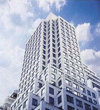
A commercial building on Madison Avenue in New York City.
Abstract The air quality in The Big Apple can result in some pretty substantial problems with rooftop cooling towers for commercial HVAC systems. Twenty years ago the owners of a large uptown commercial building on Madison Avenue, NYC decided to include an automatic self-cleaning screen filter in their new HVAC system to ward off likely problems with water quality. Today, the big roof-mounted 900 ton cooling tower continues to acts as a large community air cleaner.
Pollen, dust, insects and smoke are scrubbed from the atmosphere by the large tower. Over forty water cooled package units use the cooling tower to condition the indoor air of this commercial building. The protection provided by the filtration system is what convinced management to replace the initial installation with an improved product fifteen years later. However, the controls for the system presented a big hurdle.
Introduction
The real estate portfolio of the building's owner includes over 200 retail, hotel, office and industrial properties containing over 38 million square feet under roof. This does not include over 80 undeveloped hectares (200 acres) of prime land in Northern New Jersey. Nearly all of these properties require some form of HVAC system to condition the air for occupants. One site in particular is located along Madison Avenue in Manhattan, NY (Figure 1) near Central Park.
Housing major offices and headquarters for many of America's leading corporations, the HVAC system has to work 100% of the time. The large cooling tower sits atop this 28-story building; however, this is no ordinary commercial building. Its exceptionally high ceilings put the roof as high as a typical 35-story downtown building. An automatic self-cleaning screen filter has been located on the full flow of water leaving the cooling tower since the HVAC system was installed nearly 20 years ago.
After cleaning up the HVAC system in 2002, the new filter has cleaned itself less than once per day for the last four years.
Initial Problem
When the building was constructed, three fixed speed 270 m3/hr (1200 gpm) pumps supplied water from the 900 ton roof mounted cooling tower to 25 direct expansion water cooled package comfort units ranging in size from 14-30 tons each. In addition, nearly 20 smaller 1-5 ton similar package units were supplied water from the same tower to cool computer rooms throughout the building. Two pumps ran continuously year-round while the third was for back-up. The building's control system for HVAC was designed to maintain a fixed pressure differential (ΔP) between the supply and return water. As package units went on and off line, a by-pass valve would be controlled to maintain the preset ΔP.
Within two years of the initial HVAC system installation, problems arose on two fronts: the controls (or lack thereof) and filter mechanics. The first indications were excessive make-up water requirements and increased chemical usage in the HVAC system. This was eventually traced back to a very high frequency of filter flushing cycles. The original automatic screen filter was operated and controlled by the hydraulic pressure of the system. No PLC, microprocessor, electro-mechanical relays or electronics of any kind were associated with the filter. The filter was under the control of a hydraulic/mechanical “black box” device that sensed differential pressure across the filter body with springs, diaphragms and tubing. The ultimate movement of the diaphragm would open a passage in the “box” that allowed a hydraulic signal to be sent to a rinse valve to start the cleaning cycle. A major issue manifesting itself with the filtration system was no means of interconnecting the filter control with the building's master controls for monitoring. Problems could occur with the filter without a way of communicating with management. The operational isolation of the filter made it a potentially devastating component in the proper function of the building's comfort system.
Many automatic self-cleaning screen pressure filters use a Programmable Logic Controller (PLC) or at least a micro-processor to provide feedback to a building's master control system of the filter's physical condition before, during and after a cleaning cycle. Either a mechanical differential pressure switch (DPS) or pressure transducers are used to determine the pressure drop across the filter screen due to accumulated debris. As the openings of the screen become blocked with debris, the velocity through the remaining openings must increase to maintain a nearly constant flow rate. The pressure drop (Δp will be used for the pressure drop or differential pressure across the filter to distinguish it from ΔP across the entire HVAC system) across the screen is proportional to the square of this velocity. Therefore the Δp versus time curve is exponential as shown in Figure 2. For most of the time between cleaning cycles, the Δp is very low and increases very gradually. But just before the initiation of a cleaning cycle, Δp increases very rapidly with a very steep curve. We will see later how this is fundamental to the control of the filter.
The chief building engineer called upon a filtration specialist from another automatic screen filter company to help him troubleshoot the filtration system. Together they found two grave problems with the filter. First the “black box” controller was installed below the filter body. This control works by receiving filter inlet and outlet pressure through small diameter tubing. The physical location of this controller and its tubing led to excessive debris accumulating and eventually clogging the tubes causing control failure. This manifested itself by either not flushing the filter when it should, thus blinding the screen, or going into continuous flushes resulting in excessive make-up water for the HVAC system. Another functional issue was intermittent lack of pressure. Depending upon certain settings of the automatic by-pass valve in the HVAC system to maintain ΔP, the pressure at the filter was often insufficient to allow the filter to clean itself during a flush cycle.
Initial Solution
The filter's “black box” was relocated to a position above the filter body to minimize debris settling in the control tubes in hopes that this would eliminate the problems. This proved futile. The filter was then stripped of its controls and a two-stage manifold and large orifice solenoid valve were provided by the helping filter manufacturer. The chief building engineer developed the control logic necessary for the filter and then acquired the services of a control design company to design the appropriate software and program it into the building's master control system. The master control would now monitor the differential pressure, Δp, across the filter itself. When this Δp reached a preset threshold the master control would close the HVAC by-pass valve, thus boosting the pressure, and send a signal to the newly installed large-orifice solenoid valve on the filter to begin the cleaning cycle. At the end of the cleaning cycle, the master control would reset the by-pass valve to its proper setting. At first all seemed well, but beware of calm seas.
Problems For Eight More Years The filter continued to clog, failing to clean itself and eventually the coating on the inside of the filter began peeling off passing debris into the HVAC system. The chief building engineer decided to replace it in 2002 to see if a different filter manufacturer could truly provide a “self-cleaning” system. The new filtera of choice was an automatic filter with 250 mm (10-inch) inlet and outlet flanges designed for 410 m3/hr (1800 gpm). The screen was of 316 stainless steel weave-wire construction with a filtration degree of 100 microns. This screen contained 9200 cm2 (1420 in2) of surface area with an open area (porosity) of 32-35%. Just prior to the time of the new filter installation, the owners replaced the existing three supply pumps with 37 KW (50 HP) VFD pumps to minimize wear and tear on the HVAC system and increase energy efficiency. At the same time, the by-pass valve for maintaining ΔP across the supply/return lines was removed and the building's master controls were reprogrammed to control the speed of the VFD pumps to maintain the proper ΔP in the system. With guidance from the filter manufacturer, the chief building engineer again called upon his control design firm to develop software that would use the building's master control center to control all functions of the new filter. The master control now was able to monitor the inlet and outlet pressure of the filter and initiate a filter cleaning cycle based on a set, but adjustable, Δp across the filter. In this application this Δp threshold was 0.5 bars (7 psig). The length of this cleaning cycle was also easily adjustable being 12 seconds for this application. The master control brings all three supply pumps to full speed when the Δp threshold is reached. It then checks to make sure the pressure at the filter is sufficient for cleaning and then initiates the cleaning cycle. After this cycle is complete, the master control checks the Δp across the filter again making sure it is low enough to deem the filter screen element “clean.” If the proper Δp (<0.15 bars or <2 psig) is sensed, the master control will reset two VFD pumps to their proper speed and shut down the third pump. If the Δp is too high, the master control will continue to repeat the cleaning cycle until the proper Δp is reached or until a preset number of cycles have occurred at which time cleaning will cease and a fault signal sent to the control command station. Under this condition the master control will speed up the supply pumps to assure proper flow to the system in spite of the accumulating resistance to flow in the clogged filter. Fortunately, this scenario has not occurred since installing the new filter.
Discussion
A description of how the newly installed filter operates is in order to fully appreciate the software in the master control system. Referring to Figure 3, dirty water enters the inlet flange then passes through the coarse screen from outside-in removing large hard objects. The pre-screened water then flows to the inside of the fine screen. As water passes from inside-out in the fine screen, solid particles are stopped if they are too large to pass through the screen openings. Clean filtered water then leaves the filter through the outlet flange. A pressure drop across the filter begins to build as more and more material loads up on the inside surface of the fine screen. When a preset Δp threshold is reached across the fine screen, the building's master control system initiates a cleaning cycle after assuring the existence of sufficient pressure. The first step in the cleaning cycle is to open the rinse valve to atmospheric pressure which quickly drops the pressure in the flush chamber. Because the hollow dirt collector connects the end openings in the nozzles to the flush chamber, water quickly moves from the nozzle openings, thought the dirt collector into the flush chamber and out the rinse valve to a drain. Since the nozzle openings are touching (optional self-adjusting nozzles) or nearly touching (standard nozzles) the screen surface, water rushes backward through the screen (outside-in) in a small area (about the size of a dime) at each nozzle with a velocity exceeding 15 m/sec (50 ft/sec). This intense energy sucks off even the stickiest material and expels it from the system though the rinse valve. The hydraulic motor then rotates the dirt collector while pressure is bled off the hydraulic cylinder moving the dirt collector linearly. The spiral movement of each nozzle on the dirt collector assures that every square centimeter of fine screen surface is sucked clean of all debris in 12 seconds. The next cleaning cycle will begin when the Δp threshold is met again or until a preset time interval has been reached. There is no interruption of the filtration process during the cleaning cycle. Following is a description of how the factory supplied control package for this new filter would normally operate had it been purchased. It includes a dry contact, pre-set but adjustable, differential pressure switch (DPS) connected to the system upstream and downstream of the filter screen element. The normal threshold setting for this DPS is 0.5 bars (7 psig). As can be seen in Figure 2, this setting is on the lower portion of the steep part of the “Δp versus time” curve. A lower setting decreases the time between cleaning cycles unnecessarily while a higher setting increases the time interval very little but rapidly increases the force trying to push particles into (or though) the screen element. This normal Δp threshold prevents all but the thinnest “slime” material from extruding through the screen element. The DPS signals a PLC or other micro-processor based controller that it is time to clean the filter. The controller opens a normally closed large-orifice solenoid valve connected to a patented two-stage manifold. The manifold has an orifice in the center so that high pressure and low pressure areas become available when the solenoid opens up the manifold to flow to more accurately control the cleaning functions hydraulically. The low pressure/high pressure differential quickly opens the rinse valves and begins the suction action at each nozzle of the dirt collector and its rotation. This same manifold then bleeds off pressure from the end of the hydraulic cylinder causing the dirt collector to slowly move linearly as previously described. An adjustable timer in the controller closes the solenoid valve after the hydraulic cylinder has had time to fully extend itself, quickly closing the rinse valves and increasing the pressure to the end of the hydraulic cylinder to move the dirt collector back to its starting position. A second adjustable timer function in the controller allows the filter to clean itself based on a specified time interval. In this case the filter will clean on Δp or time, whichever comes first. The filter can also be cleaned based on a specified volume of water or by manually initiating it at the control panel. Whether the cleaning cycle is initiated by time, Δp, volumetric flow or a built-in manual function, the timer will reset itself back to zero to prevent unnecessary cleaning cycles. Should the filter not be able to clean itself after repeated cycles within an adjustable time period, the controller will halt the cleaning process to conserve water in the system and send a signal to a light, buzzer or central DCS to indicate a problem or it can open an automatic by-pass valve to send unfiltered water downstream. In other applications, the controller can operate an outlet valve to stop the flow downstream of the filter during the cleaning cycle to boost the pressure inside the filter. A single standard controller can operate up to ten filters on a common manifold. On a multiple filter system the DPS is connected to the inlet and outlet manifolds. When the Δp across the manifolds reaches the preset threshold, the first filter will clean itself and then the second filter and on down the line sequentially until all filters have been cleaned.1 This type of filter can usually be mounted right on the piping system with no other saddles, hangers or supports necessary. Therefore, they fit into very compact spaces as opposed to granular media tanks which need space and a substantial base for support. Pressure loss across granular media filters ranges from about 0.7 bars (10 psi) when clean to 1.4+ bars (20+ psi) when cleaning in required. The filtration degree of sand media filters depends on the type and grade of granular media. Media is available to remove particles as small as 0.5 micron but more commonly used media in granular filters are rated 10-40 microns.2 An automatic self-cleaning screen filter will clean more often than a granular media filter but will generally send only about half as much water down the drain over an extended period of time. The fact that self-cleaning screen filters are automatic is sufficient to guarantee their preference to basket strainers, wye-strainers and other manual filters in most cases. Centrifugal separators are often used on HVAC systems but they can only remove materials that have specific gravities considerably greater than water (s.g.=1.0). Because of their dynamic processes, the removal efficiency increases as the specific gravity increases.3 Unfortunately, cooling towers contain, among other things, organic materials that are made mostly of water and have a specific gravity very close to 1 so they cannot be removed by this technology. Centrifugal separators also are designed for a very narrow range of flow rate and many HVAC systems use VFD pumps with flows varying by an order of magnitude. Screens, on the other hand, present a positive barrier to particles that are larger than the openings of the screen regardless of their weight or specific gravity (assuming the Δp is not sufficient to cause extrusion). As large particles begin to form a layer, called a filter cake, on the screen surface, this filter cake begins to act as an even finer filter capturing particles much smaller than the screen openings. The ratio of fine particle sizes captured by the filter cake and the size of the screen openings is called the capture ratio and can be in the vicinity of 1:10 for automatic screen filters. This means that the filter cake will improve the filtration process by retaining particles one order of magnitude smaller than the screen openings themselves. Of course this capture ratio falls to 1:1 just after a cleaning cycle when no filter cake exists.
Summary
The chief building engineer and his colleagues struggled with the old filter on the HVAC system at the uptown Manhattan high-rise for nearly 15 years. Working with filtration and control specialists, they managed to keep the old system operating marginally, by scrapping the original “black box” controller and designing a make-do system using the building's master controls. In 2002, the struggling filter was beyond salvage. A new system was installed integrating a new water filter, three large VFD water supply pumps and all the functions of a 900 ton HVAC 5 together under the control of the Building Management System. The volume of water expelled to drain with the debris from the screen is often of critical importance. This filter model uses less than 280 liters (<75 gallons) per cleaning cycle. After cleaning up the HVAC system in 2002, the new filter has cleaned itself less than once per day for the last four years. The two online VFD pumps generally discharge 225 – 275m3/hr (1000 - 1200 gpm) through the HVAC system, a little less than half their maximum capacity. Because all three pumps increase to maximum speed during the cleaning cycle, the HVAC system actually sees a slight increase in pressure during the short cleaning cycle of the filter. Four years of operation under the new system has lowered energy consumption, decreased make-up water requirements, and saved on chemical costs while improving system performance.