Cooling Towers Water Filtration Solutions
In certain areas, it may prove impossible to use a large surface water source to provide adequate cooling water. Some examples include the lack of a suitable source in close proximity, increasingly stringent regulations which prohibit the use of surface water for once through cooling, etc. The requirement is then for a system which will provide a constant supply of cooling water, without requiring a large external water source. Cooling towers are the most common solution when faced with this problem.
Although cooling towers can exist in many forms, they all involve the main principle of exposing as much surface area of the water as possible to a draft of ambient air. This usually involves spraying the water over a series of baffles or similar material. As the water travels down through the tower, it impacts successive layers, which break the water droplets apart, exposing more and more surface area. At the same time, an ambient airstream is either forced or induced, usually in a counterflow or cross flow direction, contacting the water and removing the excess energy.
The cooling tower is a source of several kinds of particulates, which could be detrimental to the system. By nature, it acts as an air scrubber, that is, any airborne particulates with which the water comes in contact are removed from the air and carried into the cooling system. In addition, organic matter can grow on the surfaces of the tower, occasionally breaking free and entering the cooling system.
Eventually, the system will need to be shut down. The tower basin will require removal of the sludge buildup and any associated heat exchangers or other equipment will require maintenance to clean the passages. Not only does this increase maintenance costs resulting in reduced profits due to unscheduled downtime but this can also increase energy costs due to decreased heat transfer efficiency.
Chemical treatment alone cannot solve the problems associated with suspended particulates in the cooling system. Relying on blowdown alone is a hit and miss proposition at best. The best approach is a combination of methods, including the use of Orival automatic self-cleaning filters.
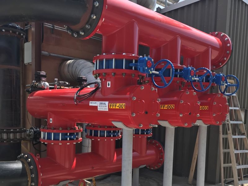
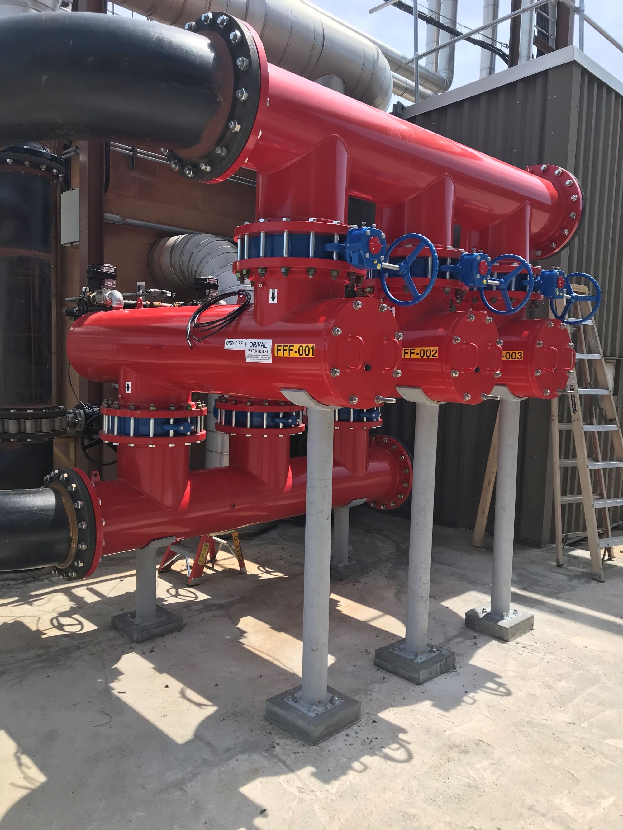
Full-Flow Cooling Tower Filtration
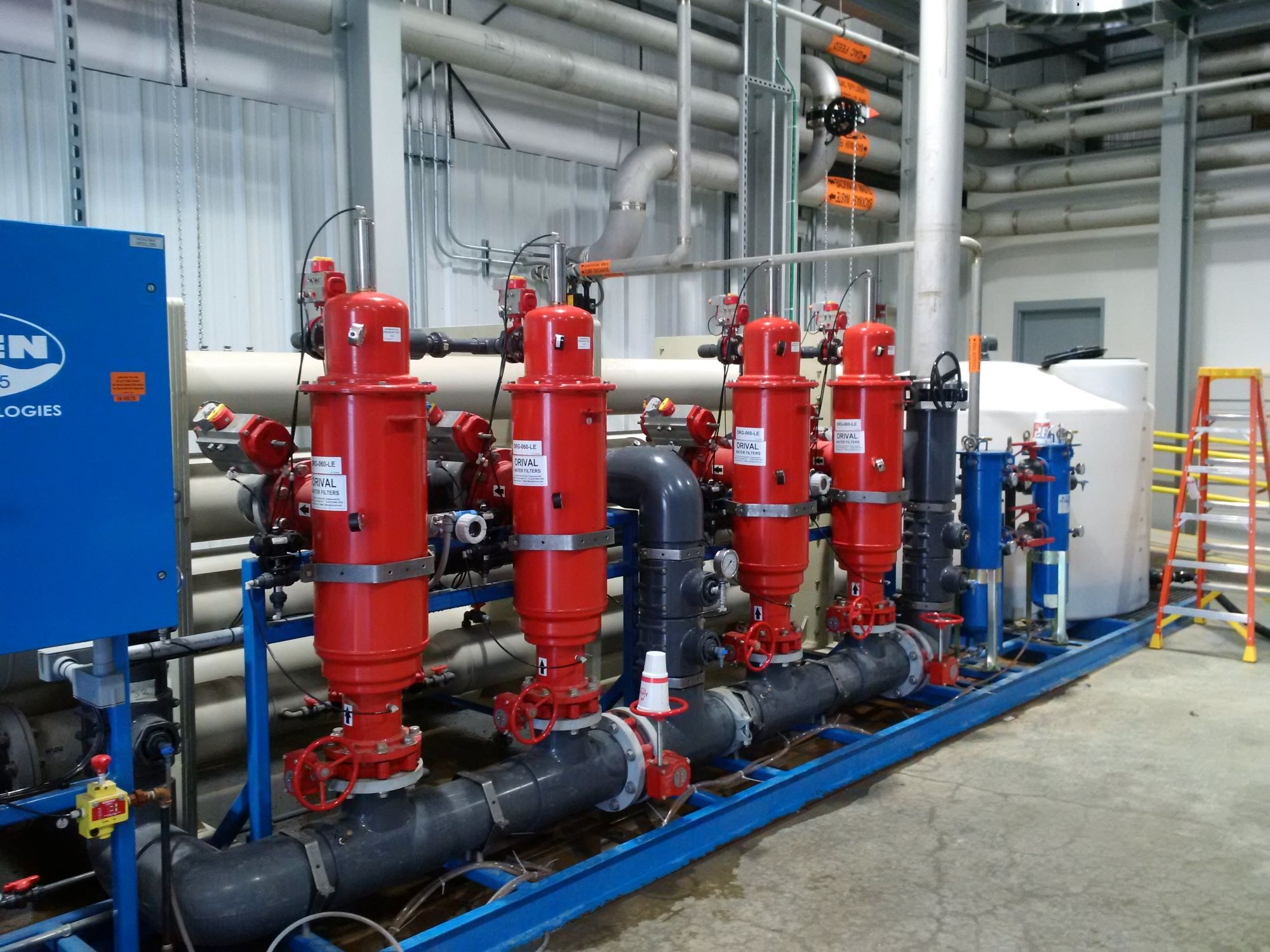
Most effective is to use a filter equipped with an automatic built-in by-pass to filter the entire flow. Filtration for a full flow system is typically in the 50-200 micron range, depending on the type of equipment being protected, water quality, environment, etc.
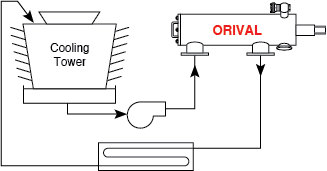
Fig. 1. Typical full-flow cooling tower filtration
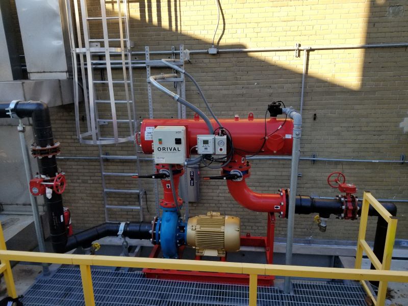
Side-Stream Cooling Tower Filtration
Alternatively, a smaller ORIVAL filter may be installed on a side-stream system to filter a portion of the main flow, typically between 5-25%. Side-stream filtration is the most used method of maintaining minimal suspended solids in a cooling system. Side-stream filtration continuously filters and removes suspended solids from a portion of the flow, and then returns the clean water back to the system, usually through the cooling tower reservoir or sump. This method maintains general control of suspended solids, it does not filter all the water going to the process.
A side-stream system might be selected over a full-flow system to keep project costs down. Filtering only a percentage of the water means you can use a smaller filtration system. Side-stream systems are also not on the main line so a pressure drop (due to solids build up on the screen) will not affect main line pressure. Therefore if constant pressure is important, a side-stream system will be beneficial.
The side-stream system may either be supplied by the main tower pumps, or by a dedicated side-stream pump. Typically, filters selected for side-stream use are equipped with large screen areas in order to increase the capturing ratio and, hence, filter efficiency. Filtration for a side-stream system is typically in the 5-200 micron range.
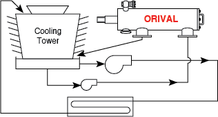
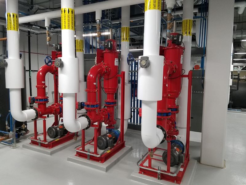
Fig. 2. Typical side-stream filtration of basin using a recirculating pump.
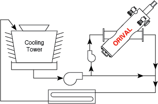
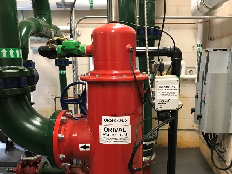
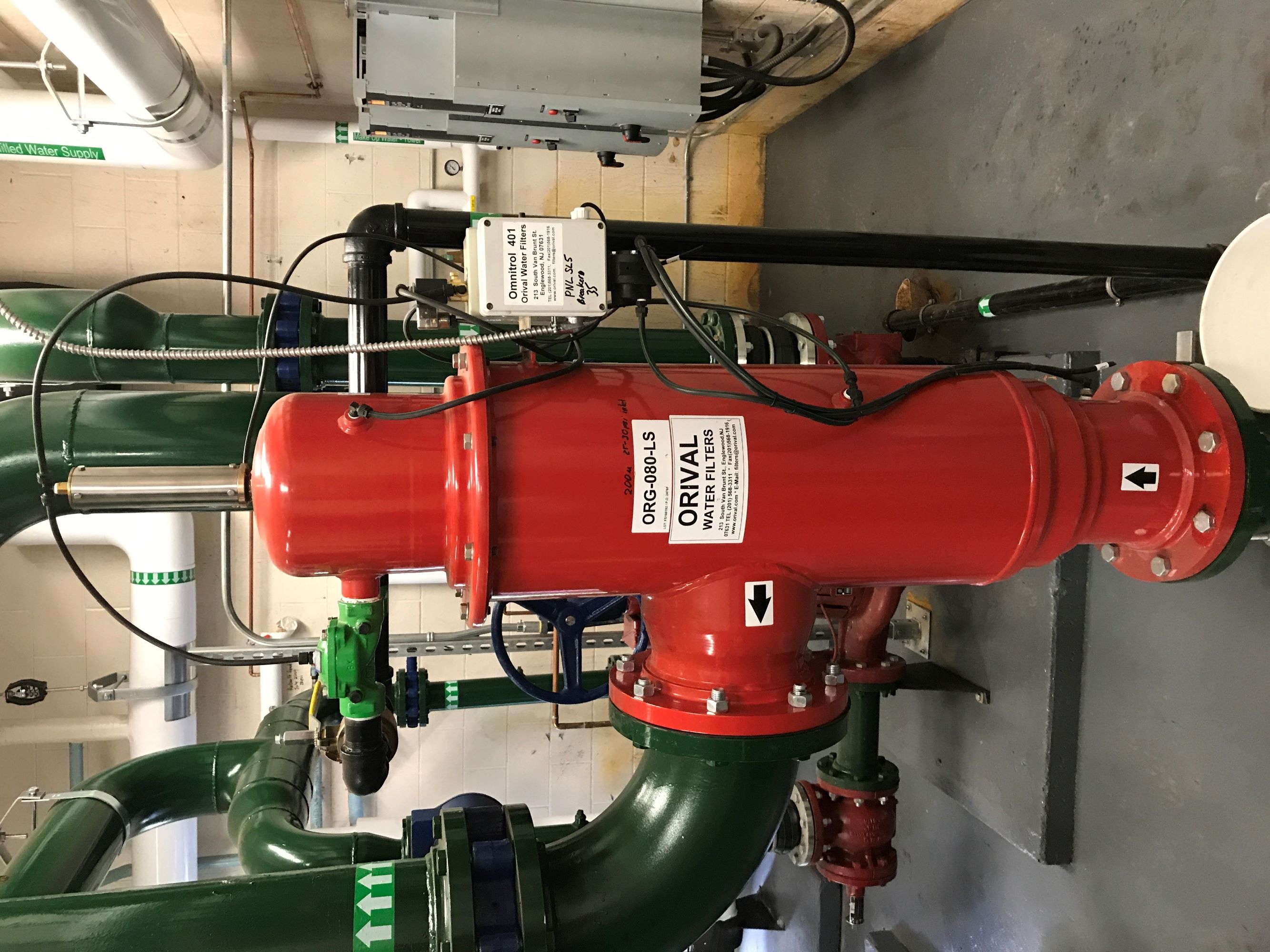
Fig. 3. Typical side-stream filtration using a booster pump.
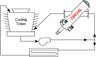
Fig. 4. Typical side-stream filtration using an existing pump.