Manufacturing Facility Chooses Automatic Self Cleaning Filter for Efficient and Effective Chiller Protection
Mar 2013, Dr. Marcus N. Allhands, PE, VP Business Development Orival, Inc.
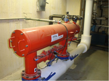
Figure 1. Filter Installation

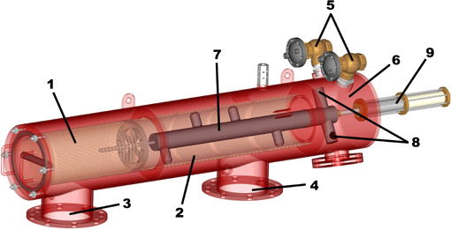
Figure 2. Filter Components
Background
Cooling towers dissipate both ambient and process heat in most large manufacturing facilities. These structures facilitate the transfer of unwanted energy (heat) from a transport liquid (usually water) to the atmosphere. Problems with efficient heat transfer, equipment protection and pathological risks to employees can most often be traced back to an issue with suspended solids. These solids can originate in the process, in the piping, from the atmosphere or from internal biological growth.
Side-stream filtration is the most commonly used method of maintaining minimal suspended solids in a cooling system. Side-stream filtration takes a portion of the flow from the system and filters it to remove suspended solids and then returns the clean water back to the system usually through the cooling tower reservoir or sump. This method maintains general control of suspended solids. It does not filter all the water going to the process. Historically, cooling systems have relied heavily on the two following established methods of suspended solids removal. Cyclonic devices are highly efficient at removing high specific gravity solids, while granular media filtration generally is more effective at removing low specific gravity organic solids. Automatic self-cleaning screen filter technology provides a solid barrier to both organic and inorganic solids regardless of specific gravity and requires very little energy to operate. In addition they conserve coolant additives by using very little coolant liquid for the self-cleaning process. The unwanted loss of coolant can be completely eliminated by incorporating the cleaning cycle into the blow-down process of the cooling system.
Application
A large producer of cigarettes and fine cut tobacco manufactures, packages and ships billions of cigarettes per year. The plant installed a new production line recently with all new equipment. One new piece of equipment was a state-of-the-art 150 ton magnetic chiller on the evaporator loop of the cooling system. Chillers are expensive components in a cooling system that must be supplied a continuous flow of clean water from a cooling tower. Therefore, all the flow going to the chiller had to be filtered to protect it from the possibility of damage induced by suspended solids. For this application a side-stream system was not appropriate. Cyclonic separators could remove the heavier solids such as sand and pipe scale but not the lighter organic and wind-blown materials. Granular media filters could remove the organic fraction of suspended solids but would have trouble with sand particles since they would tend to stay in the filter vessel during the cleaning cycle. Also, these filters need to be taken offline during each cleaning cycle and require an appreciable amount of water for cleaning.
Fully automatic self-cleaning screen filters provide an economical means of removing suspended solids from cooling tower water.
Solution
An internationally known manufacturer of filtration equipment was asked to recommend a filtration system to protect the chiller from airborne debris scrubbed from the atmosphere by the cooling tower and other solids originating within the cooling system. The solution had to take into account that the system was likely to contain both organic and inorganic solids and that a continuous flow of water must be delivered to the chiller at all times. Pressure losses had to be kept to a minimum and flow rates could not vary appreciably. A fully automatic self-cleaning filter with 6 inch inlet and outlet flanges and a 200-micron stainless steel screen element was recommended for the application. The filter has a built in bypass system that will automatically open a bypass line around the filter element should anything cause the filter to fault. A filtration degree of 200-micron was determined to be most appropriate for this application to remove particles capable of causing damage to the new chiller. This means the openings in the screen are a little larger than the diameter of a human hair and will remove airborne particulates, microbiological growth, pollen and other materials found in most cooling towers. Figure 1 shows the final installation with the built-in bypass system.
Operation
The filtration unit consists of two stages of filtration. The components of a typical filter of this type are depicted in Figure 2. The first is a coarse cylindrical pre-filter (1) to remove rigid particles that are too large to pass through the nozzles of the dirt collector during the cleaning cycle. The second stage is a cylindrical stainless steel weave-wire fine screen element (2) that is the real work-horse of the filter. The openings of this element are of a specific size representing the filtration degree of the element (200 microns in this application).
Dirty water enters the inlet flange (3) and then passes through the coarse screen described above from outside in and then passes into the center of the fine screen element. Water passes through this fine screen from the inside out and exits through the outlet flange (4).
Unwanted solids accumulate on the inner surface of the fine screen element. As this debris layer builds, energy is dissipated causing a pressure differential across the screen. When the control system senses this differential pressure reaching a pre-set threshold (7 psi or 0.5 bars in this case) the cleaning cycle is initiated. The first step in the cleaning cycle involves the automatic opening of the rinse valves (5) to atmosphere. A pipe carries this flush water to a drain but oversized piping is used to prevent backpressure against these rinse valves. When these valves open the pressure in the hydraulic motor chamber (6) and the dirt collector (7) drops abruptly. The pressure just inside the nozzle openings on the dirt collector is nearly zero gauge pressure since these nozzles are connected through the dirt collector, hydraulic motor chamber and rinse valves to the atmosphere outside the pressurized filter body. Water inside the filter rushes into the nozzles at very high velocity and passes through the dirt collector into the hydraulic motor chamber and out the rinse valves. The nozzle openings on the dirt collector are within a few millimeters of the fine screen surface causing water to pass backward through the screen in a very small area at very high velocity dislodging the filter cake (debris built up on the inside screen surface) and sucking it into the dirt collector. Since only a very small area of the screen is being cleaned by each nozzle (an area about the size of a dime), there is plenty of energy available for vacuuming debris from the screen. This debris is discharged along with a small amount of water through the rinse valves to the drain. As water rushes out of the dirt collector into the hydraulic motor chamber it passes through the hydraulic motor (8) imparting a rotation to the dirt collector and thus moving the cleaning nozzles around the inside surface of the screen. A hydraulic piston (9) then slowly moves the dirt collector linearly giving the rotating nozzles a spiral movement in such a way that every square inch of screen surface is passed by a suction nozzle assuring that the entire filter cake is vacuumed from the screen during the cleaning cycle. This entire process takes less than 10 seconds and does not interrupt the flow of clean water downstream.
Summary
Fully automatic self-cleaning screen filters provide an economical means of removing suspended solids from cooling tower water. The use of weave-wire screens as the filtering media provides a positive removal system eliminating all particles larger than the filtration degree of the screen from the cooling system and many smaller particles due to the filtration effect of the filter cake that builds on the screen element surface between cleaning cycles. This phenomenon of filtration improvement can be loosely quantified as removing particles down to about one tenth (1/10) the size of the screen filtration degree when the filter cake is at its thickest. This 1:10 relationship is called the capture ratio as employed in screen filtration systems. The efficient suction cleaning principle allows the filter cake to be removed completely from the screen surface within seconds without physically touching the cake or screen. During the suction cleaning cycle the filtration process is uninterrupted; thereby, providing filtered water downstream of the filter at all times eliminating the need for redundant equipment. Water and chemical losses are kept to a minimum and organic and inorganic solids are removed with equal efficiency. Since only a small pressure differential occurs across the screen element, the extrusion of soft organic material through the screen is prevented. If any problem should occur with the filter, the controller will sense this and open the built-in bypass valve to provide a continuous flow of water to the new chiller. The controller will then send a signal to notify personnel of the problem for resolution. Routine maintenance is minimal consisting of a monthly inspection of the rinse valves to see that they are seating properly and an annual inspection of the screen and hydraulic piston. An occasional manually-induced cleaning cycle by maintenance personnel is recommended to assure proper operation. Full stream protection, automatic self-cleaning process, automated bypass system and low maintenance were just the qualities the engineers were looking for in a protection system for the new magnetic chiller.